
Switch Mode Power Supply (SMPS) Transformers
Introduction
These are essential components for high-efficiency power conversion.
SMPS transformers are a critical component in Switch Mode Power Supplies (SMPS) and DC/DC converters, playing a key role in efficient power conversion. These transformers are designed to handle high-frequency operation, which is fundamental to the functionality of modern power supplies.
In an SMPS, the transformer is responsible for stepping up or stepping down the input voltage while maintaining high efficiency and low energy losses. Unlike traditional linear power supplies, which rely on heavy transformers operating at mains frequency, SMPS transformers operate at much higher frequencies (typically between 20 kHz and 1 MHz), which allows for significantly smaller and lighter designs without sacrificing performance.
SMPS transformers are designed to provide:
- Voltage Conversion: Stepping voltage up or down based on the requirements of the load while maintaining minimal power loss.
- Isolation: Electrical isolation between the input and output, crucial for safety, noise reduction, and signal integrity.
- Efficient Power Transfer: High-frequency operation allows for compact designs with improved power transfer efficiency, reducing the size and weight of the power supply unit.
- Low Ripple & Noise: These transformers help reduce electromagnetic interference (EMI) and minimize ripple in output voltage, ensuring stable performance in sensitive electronic circuits.
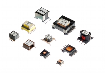
Common ferrite types are EFD, ETD, EP and RM.

EFD Transformers
EFD Transformers: Compact, High-Performance Solutions for SMPS Applications
EFD transformers are engineered with compact, high-efficiency cores designed to maximize magnetic coupling while minimizing physical footprint. These transformers are particularly well-suited for Switched-Mode Power Supply (SMPS) applications, where efficient space utilization is critical.
The unique EFD core design enables a significantly smaller transformer size without compromising on performance or energy efficiency. This is essential in modern electronics, where devices are becoming increasingly compact, yet still require effective power conversion within constrained spaces.
By leveraging the EFD core's high magnetic coupling, these transformers offer excellent energy efficiency, reduced heat generation, and improved overall performance. Their small form factor makes them ideal for use in a wide range of applications, from portable devices to high-performance electronics, where every millimeter of space counts without sacrificing power efficiency or reliability.
With their ability to deliver high performance in a small package, EFD transformers are an optimal choice for powering the next generation of compact, energy-efficient electronic devices.
Typical EFD Sizes
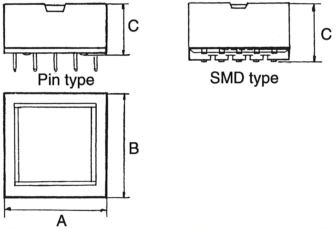
| Type | A | B | C | Type | Pin hole config. | SMD Pad config. |
| EFD 10 | 12 | 19 | 5.7 | SMD |  | |
| EFD 12 | 14 | 21 | 6.5 | SMD |  | |
| EFD 15 | 16 17 | 17.5 23 | 8.0 8.0 | Pin SMD |  |  |
| EFD 20 | 21.5 22 | 24 28 | 10.0 10.0 | Pin SMD |  |  |
| EFD 25 | 26 | 29 | 12.5 | Pin |  | |
| EFD 30 | 31 | 34 | 12.5 | Pin |  |
Typical EFD Power Capacities
| Size | f kHz | Push-pull W | Forward W | Flyback W |
| EFD 10 | 100 | 8-12 | 3-5 | 2-4 |
| EFD 12 | 100 | 10-16 | 5-8 | 4-7 |
| EFD 15 | 100 | 15-25 | 8-14 | 7-12 |
| EFD 20 | 100 | 50-70 | 30-45 | 25-40 |
| EFD 25 | 100 | 70-130 | 60-90 | 50-80 |
| EFD 30 | 100 | 130-200 | 80-150 | 70-120 |
ETD Transformers
ETD transformers are engineered to provide an optimal balance between core and copper losses, resulting in high efficiency and reliable thermal performance.
Their core geometry allows for efficient winding utilization, reduced leakage inductance, and improved magnetic coupling, enabling compact designs with high power density.
ETD transformers also exhibit good thermal stability and versatility across a wide operating frequency range, making them well-suited for high-performance power electronics applications, particularly in switching power supplies and DC-DC converters.
Typical ETD Sizes
| Type | A | B | C | Horizontal Vertical | Pin hole Horizontal | Pin hole Vertical |
| ETD 19 | 24 31 | 33 19 | 20 37 | H V |  |  |
| ETD 24 | 29 36 | 34 21 | 22 38 | H V |  |  |
| ETD 29 | 36 43 | 36 24 | 26 43 | H V |  |  |
| ETD 34 | 40 47 | 43 27 | 35 45 | H V |  |  |
| ETD 39 | 45 52 | 48 29 | 38 50 | H V |  |  |
| ETD 44 | 50 57 | 53 32 | 41 55 | H V |  |  |
| ETD 49 | 55 62 | 58 34 | 43 59 | H V |  |  |
| ETD 54 | 62 68 | 62 37 | 46 66 | H V |  |  |
| ETD 59 | 67 73 | 67 39 | 50 70 | H V |  |  |
Typical ETD Power Capacities
| Size | f kHz | Push-pull W | Forward W | Flyback W |
| ETD 29 | 100 750 | 100-200 250-430 | 100-160 200-300 | 80-140 150-250 |
| ETD 34 | 100 750 | 200-360 400-650 | 150-250 300-400 | 100-200 250-400 |
| ETD 39 | 100 750 | 300-500 600-1000 | 200-350 400-700 | 200-330 400-600 |
| ETD 44 | 25 100 | 250-400 500-900 | 100-240 400-600 | 120-200 300-530 |
| ETD 49 | 25 100 | 400-630 800-1300 | 200-350 600-900 | 200-320 500-800 |
| ETD 54 | 25 100 | 500-900 1200-2000 | 300-550 800-1400 | 300-500 750-1250 |
| ETD 59 | 25 100 | 800-1500 2000-3500 | 600-900 1500-2400 | 500-800 1300-2000 |
ETD transformers are also available in potted versions, either for horizontal or vertical mounting. Ask for more details on this.
EP Transformers
EP transformers feature a highly compact design, making them ideal for applications requiring high inductance in a limited space, such as filter chokes, pulse transformers, and small power transformers.
The unique core geometry not only enables high winding packing density and efficient magnetic utilization but also provides excellent natural shielding against electromagnetic interference (EMI).
This combination of compactness, low leakage flux, and effective shielding makes EP transformers particularly suitable for use in sensitive electronic circuits and densely packed assemblies.
Typical EP Sizes
| Type | A | B | C | Type | Pin hole config. | SMD Pad config. |
| EP 7 | 9.5 9.5 | 7.5 12.5 | 9.5 8.5 | Pin SMD |  |  |
| EP 10 | 11 13 | 11 14.5 | 12.0 10.3 | Pin SMD |  |  |
| EP 13 | 14 13 | 14 20 | 13 12 | Pin SMD |  |  |
| EP 17 | 19 | 19 | 16 | Pin |  | |
| EP 20 | 27 | 23 | 21 | Pin |  |
Note: When mounting clips with ground pins, the dimensions A, B and C will be slightly increased accordingly.
RM Transformers
RM transformers are widely used in applications such as filter chokes, low-frequency and pulse transformers, as well as high-frequency power transformers in power supplies up to approximately 600 W.
Their optimized core geometry allows for high power density, low leakage inductance, and efficient use of PCB space, making them well-suited for compact designs.
Surface-mount RM cores are also available, enabling their use as miniature power transformers and chokes operating at frequencies approaching 1 MHz.
Typical RM (3-7) Sizes
| Type | A | B | C | Type | Pin hole config. | SMD Pad config. |
| RM 3 | 7.4 | 7.8 | 7.5 | 1 |  | |
| RM 4 | 9.8 11.0 | 11.0 15.5 | 10.5 8.0 | 1 SMD |  |  |
| RM 4L | 9.8 13.6 | 11.0 17.0 | 8.5 8.0 | 1 SMD |  |  |
| RM 5 | 12.3 14.2 | 14.6 19.0 | 10.5 10.7 | 1 SMD |  |  |
| RM 5L | 14.2 | 18.9 | 8.0 | SMD |  | |
| RM 6 | 14.7 16.3 15.5 | 17.9 24.9 22.0 | 12.5 13.0 12.7 | 1 2 SMD |  |  |
| RM 7 | 17.8 | 20.3 | 13.5 | 1 |  |
Typical RM (8-14) Sizes
| Type | A | B | C | Type | Pin hole Type 1 | Pin hole Type 2 |
| RM 8 | 19.7 23.5 | 23.2 29.9 | 16.5 16.5 | 1 2 |  |  |
| RM 10 | 24.7 23.3 | 28.5 39.4 | 18.7 19.1 | 1 2 |  |  |
| RM 12 | 29.8 28.4 | 37.6 45.2 | 24.6 23.7 | 1 2 |  |  |
| RM 14 | 34.8 31.4 | 42.2 29.2 | 30.2 48.4 | 1 2 |  |  |
| RM 12 2-Part BOBBIN | 40.3 | 35.1 | 31.1 | 3 |  | Dimensions defined as per type 2 |
| RM 6/45 RM 8/45 | 27 27 | 27 28 | 16 20 | 4 4 |  |  |
| RM 6- RM 14 | Low-profile cores are also available for these types | |||||
Typical RM Power Capacities
| Size | f kHz | Push-pull W | Forward W | Flyback W |
| RM4 | 100 750 | 10-16 20-30 | 5-8 10-20 | 4-7 10-18 |
| RM5 | 100 750 | 15-25 30-45 | 8-14 20-30 | 8-12 20-30 |
| RM6 | 100 750 | 30-40 50-80 | 20-30 40-55 | 15-25 30-50 |
| RM7 | 100 750 | 40-60 60-110 | 25-40 50-80 | 20-35 40-65 |
| RM8 | 100 750 | 50-80 100-160 | 40-60 70-110 | 30-50 60-100 |
| RM10 | 100 750 | 80-150 150-280 | 60-100 120-200 | 50-90 100-170 |
| RM12 | 100 750 | 130-220 200-400 | 90-150 200-300 | 70-130 150-250 |
| RM14 | 100 750 | 200-340 400-600 | 130-240 300-450 | 120-200 250-400 |
Custom Design
LINTRON offers a broad range of transformer types, sizes, and form factors to meet diverse application requirements.
Our product portfolio covers power ratings from 1 W to 6000 W, with options for both through-hole and surface-mount (SMD) configurations.
This flexibility allows for optimized integration into designs ranging from low-power signal applications to high-power conversion systems.
For detailed specifications, custom solutions, or application support, please contact us.
Lintron Electronics Ltd, Unit 6b, Wansbeck Bus Pk, Ashington, NE63 8QW, England | Tel: +44 (0) 1670 811888 |
© 1996-2025 Lintron Electronics Ltd. All Rights Reserved. LINTRON is a Trade Mark.